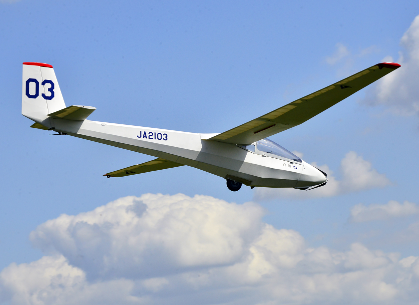
Believing that the Mita type 3 is not popular in the Europian glider community, let me introduce her.
The Mita type 3 mod.1 was designed by Mr. Asahi Miyahara in 1965 and took the first flight in 26th March, 1966.
It is two placed soarer used by many flying clubs and brought up many glider pilots in Japan.
General characteristics
1. Crew 2
2. Length 8.60m
3. Wing Span 16.0m
4. Height 1.3m
5. Wing Area 15.9m^2
6. Aspect Ratio 16.1
7. Airfoil NACA 633-618
8. Empty Weight 300Kg
9. Gross Weight 450Kg
10. Number of Production 32
Performance
Vne 180Km/h
Max glide ratio 30.8
Rate of sink 0.75m/sec
Last edited by norm on 15 Nov 2019, 10:43, edited 1 time in total.
Cliff, yes I made the plan by myself using 2D CAD.
My 1/3 scale Mita type 3 has 5.33m wing span and the all-up weight is just around 10Kg. It has a fuselage made of epoxy bonded carbon pipes and covered with the SIG KOVERALL. The original Mita's fuselage is made of welded steel pipes and covered with cloth.
Because the 1/3 model craft's Reynolds Number is much lower than the original Mita, I changed the NACA 633-618 18% thickness airfoil to the NACA 632-615 airfoil which has 15% thickness. It was decided after the study of airfoil characteristics change at low Reynolds number by using the XFLR5 software.
Attachments
fuselage structure
Last edited by norm on 19 Nov 2019, 13:58, edited 4 times in total.
Cliff,
It is my pleasure and a great honor to donate the plan but the current plan is quite messy. After organizing it I will donate. Please wait.
Paul and Stephen B,
The fuselage structure was made of carbon tubes bonded by epoxy adhesive. After cutting the tubes, edges were trimmed carefully by a diamond file to fit well. The fuselage is composed from several truss panels. Each panel was built on a flat plate onto which the plan was placed. Attached is a shot of making a panel.
At this point, a bit of CA is dropped on each junction. After making necessary panels, then they were constructed. Second photo shows this process.
A bit of CA is dropped again. After the construction is completed, the epoxy adhesive is applied on each junction. The epoxy adhesive was mixed with a carbon powder.
The canted longerons were joined each other with a steel rod inserted inside with the epoxy adhesive.
Attachments
assembling aft fuselage
making fuselage panel
Last edited by norm on 19 Nov 2019, 14:03, edited 3 times in total.